Linggo, Marso 04, 2012

Chapter 27: Low−Earth−Orbit Satellites (LEOs)

Low-Earth-Orbits
     Private companies are striving to provide truly seamless global communications to the public, making today’s personal communication systems (PCS) a proving ground for new technologies. This global approach has sparked the development of several new communication satellite systems, which abandon the traditional use of geostationary earth orbit (GEO) in favor of medium earth orbit (MEO) and low earth orbit (LEO) satellite systems. LEO and MEO satellite networks increase the service regions of their designers, providing services to regions of the world where there is little or no telecommunication infrastructure, such as Asia, Africa, Eastern Europe, South America, and the polar regions. These LEO and MEO satellite networks provide global coverage to their users, which a typical GEO satellite system cannot provide. One such LEO satellite system, Motorola’s IRIDIUM system, was completely deployed in May 1998.
     In December 1990, Motorola filed an application with the FCC for the purposes of constructing, launching, and operating a LEO global mobile satellite system known as Iridium. This was the hot button that sparked the world into a frenzy. Iridium was a concept of launching a series of 66 satellites around the world to provide global coverage for a mobile communications service operating in the 1.610 to 1.6265 GHz frequency bands. The concept was to use a portable or mobile transceiver with low profile antennas to reach a constellation of 66 satellites. Each of the satellites would be interconnected to one another through a radio communications system as they traversed the globe at 413 nautical miles above the earth in multiple polar orbits.This would provid worldwide coverage, much similar to an orange slice concept . This would provide a continuous line−of−sight coverage area from any point on the globe to virtually any other point on the globe, using a spot beam from the radio communications services on−board each of the satellites.

    The main component s of the IRIDIUM system are the satellites, gateways, and user handsets. The satellites utilize inter-satellite links (ISLs) to route network traffic. Regional gateways will handle call setup procedures and interface IRIDIUM with the existing public switched telephone network (PSTN). A dual-mode handset will allow users to access either a compatible cellular telephone network or IRIDIUM.  IRIDIUM will give the user the capability to receive persona l communications worldwide using a single telephone number. It is designed to augment the existing terrestrial and cellular telephone networks. IRIDIUM is expected to provide cellular-like service in areas where terrestrial cellular service is unavailable, or where the PSTN is not well developed.

Network Connectivity
    Communication networks are commonly represented by graphs of nodes, which represent communication locations,and links,which represent communication transmission paths. The IRIDIUM network essentially has two planes of nodes, the satellites and the earth stations, which are moving with respect to each other. As a result, the links connecting earth stations to satellites change over time. 
    In the IRIDIUM network, a link is established from an earth station to the satellite with the strongest signal. The satellites are moving much faster than the mobile users. Mobile user scan be considered stationary with respect to the velocity of the satellites, as even a mobile user in an airplane is travelling much slower than a satellite. As the satellites pass overhead, the link from earth station to satellite is handed off from a satellite leaving the user’s area to one entering the user’s area.

System Capacity
   The IRIDIUM system uses a combination of time division multiple access ( TDMA) and frequency division  multiple access (FDMA). The TDMA frame is 90 ms long and it contains four full-duplex user channels at a burst data rate of 50 kb/s.The four full-duplex channels consist of four uplink time slots and four downlink time slots. The IRIDIUM system will support full-duplex voice channels at 4800 b/s and half-duplex data channels at 2400 b/s. The specific details of the TDMA frame, such as the number of framing bi ts and the length of a user time slot, are not published in open literature. In addition, the type of voice encoding that will be used to provide acceptable voice quality at 2400 b/s is proprietary and is not published in open literature. 

Call Processing
     The IRIDIUM system will allow users to roam worldwide and still utilize a single subscriber number. To accomplish this, each user will have a home gateway that normally provides his service. The gateways in this system will be regional and will support large geographical areas. An IRIDIUM subscriber is uniquely identified by three numbers: the mobile subscriber integrated services digital network number (MSISDN), the temporary mobile subscriber identification (TMSI), and the IRIDIUM mobile subscriberidentity (IMSI). 

      The MSISDN is the telephone number of an IRIDIUM subscriber. The MSISDN is five digits long, and makes up part of the twelve-digit number dialed to reach a subscriber. The first field of the twelve-digit number is the four-digit country codeThe second field of the number is a three-digit geographical code. This code will be used to identify a user’s home country in  regions where one gateway services mor e than one country. The third and final field of the number is the MSISDN. The TMSI is a temporary number that is transmitted over the network during call setup. This number is changed periodically to protect subscriber confidentiality.

Watch this video for more information.

             http://www.deetc.isel.ipl.pt/sistemastele/ST1/arquivo/IRIDIUM%203.pdf
             Broadband Telecommunications Handbook (VPN 3GW GPRS MPLS VoIP SIP).pdf

Chapter 25: Third−Generation (3G) Wireless Systems

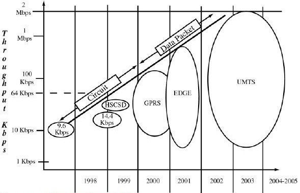
As the convergence of wireless technology and the Internet continue at an escalating pace, the new possibilities created by 3G and 4G technologies appear endless. Preparing for the revolution, existing Time Division Multiple Access (TDMA) operators must evolve their networks to take advantage of Mobile Multimedia applications and the eventual shift to an all−IP architecture. One way to do that is through the evolution of General Packet Radio Services (GPRS). However, soon after we see the installation of GPRS, some operators will begin the next step in the evolution process to Enhanced Data for Global Environment (EDGE).

Capabilities & service attributes that are expected from 3G systems


Time line for 3G/UMTS

GPRS
     Probably the most important aspects of GPRS are that it enables data transmission speeds up to 170 Kbps, it is packet based, and it supports the leading data communications protocols (IP and X. 25). GPRS operates at much higher speeds than current networks, providing advantages from a software perspective. Wireless middleware currently is required to enable slow speed mobile clients to work with fast networks for applications such as e−mail, databases, groupware, or Internet access. With GPRS, wireless middleware will probably be unnecessary, making it easier to deploy wireless solutions.

Because there is minimal delay before sending data, GPRS is ideally suited for applications such as
              · Extended communications sessions
              · E−mail communications
              · Chat
              · Database queries
              · Dispatch
              · Stock updates
                                 GPRS Network Architecture

EDGE

     EDGE, Enhanced Data rates for GSM Evolution, is a further step for GSM to migrate to 3G. It uses a new air-interface technology -- 8 Phase Shift Keying Modulation (8-PSK) to offer 48 kbits/s per GSM timeslot. The overall offered data speeds of 384Kbps places EDGE as an early pre-taste of 3G and it is actually labeled as 2.75G by the industry.
     EDGE is occasionally referred to as Enhanced GPRS (EGPRS) because it increases the capacity and data throughput of GPRS by three to four times. Like GPRS, EDGE is a packet-based service, which provides customers with a constant data connection.
     For EDGE to be effective it should be installed along with the packet-switching upgrades used for GPRS. This entails the addition of two types of nodes to the network: the gateway GPRS service node (GGSN) and the serving GPRS service node (SGSN). The GGSN connects to packet-switched networks such as internet protocol (IP) and X.25, along with other GPRS networks, while the SGSN provides the packet-switched link to mobile stations.
     By providing an upgrade route for GSM/GPRS and TDMA networks, EDGE forms part of the evolution to IMT-2000 systems. Since GPRS is already being deployed, and IMT-2000 is not expected until 2002, there is a definite window of opportunity for EDGE systems to fill in as a stop-gap measure.

EDGE Network Architecture

UMTS
     Universal Mobile Telecommunications System (UMTS) is one of the third-generation (3G) cell phone technologies. Currently, the most common form of UMTS uses W-CDMA as the underlying air interface. It is standardized by the 3GPP, and is the European answer to the ITU IMT-2000 requirements for 3G cellular radio systems.
      UMTS is packet-based and it allows transmission of text, digitized voice, video, and multimedia at data rates up to 2 megabits per second (Mbps). UMTS offers a consistent set of services to mobile computer and phone users, no matter where they are located in the world.

EDGE Network Architecture
     A UMTS network consists of three domains; Core Network (CN), UMTS Terrestrial Radio Access Network (UTRAN) and User Equipment (UE). The main function of the core network is to provide switching, routing and transit for user traffic. Core network also contains the databases and network management functions.
      The basic Core Network architecture for UMTS is based on GSM network with GPRS. All equipment has to be modified for UMTS operation and services. The UTRAN provides the air interface access method for User Equipment. Base Station is referred as Node-B and control equipment for Node-B's is called Radio Network Controller (RNC).

              Broadband Telecommunications Handbook (VPN 3GW GPRS MPLS VoIP SIP).pdf

Chapter 24:General Packet Radio Service (GPRS)


     The introduction of wireless communication has allowed many people around the world to live their lives and conduct business in ways that were never before possible.Millions of cellular subscribers have become accustomed to always having a telephone with them wherever they go.Now, businesses are wanting to be able to connect to the office when they are out of the office so they can check their email, search on the Internet, access company files, send faxes and data whenever and wherever it is needed.Currently, there are numerous wireless data services available, but a new technology, General Packet Radio Service, offers much excitement to consumers. Indeed, the demand for communications and new technology is greatly growing based on the needs of the people and business especially in the Internet.

What is GPRS?
     General Packet Radio Service, more commonly known as GPRS, is a new non-voice, value added, high-speed, packet-switching technology, for GSM (Global System for Mobile Communications) networks. It makes sending and receiving small bursts of data, such as email and web browsing, as well as large volumes of data over a mobile telephone network possible. A simple way to understand packet switching is to relate it to a jigsaw puzzle. Image how you buy a complete image or picture that has been divided up into many pieces and then placed in a box. You purchase the puzzle and reassemble it to form the original image. Before the information is sent, it is split up into separate packets and it is then reassembled at the receivers end. The main benefits of GPRS are that it reserves radio resources only when data is available to send, and it reduces the reliance on traditional circuit−switched networks.

       GPRS offers a continuous connection to the Internet for mobile phone and computer users. Users may need to be connected to a data communication network (such as a LAN, WAN, the Internet, or a corporate Intranet), but that does not mean they are sending and receiving data at all times. Data transfer needs are not generally balanced.In the majority of cases, users will tend to send out small messages but receive large downloads.Therefore, most of the data transfer is in one direction. GPRS is expected to provide a significant boost to mobile data usage and usefulness. It is expected to greatly alter and improve the end-user experience of mobile data computing, by making it possible and cost-effective to remain constantly connected, as well as to send and receive data at much higher speeds than today.Its main innovations are that it is packet based, that it will increase data transmission speeds, and that it will extend the Internet connection all the way to the mobile PC – the user will no longer need to dial up to a separate ISP. 

Method of Operation

       GPRS gives GSM subscribers access to data communication applications such as e-mail, corporate networks, and the Internet using their mobile phones.The GPRS service uses the existing GSM network and adds new packet-switching network equipment. GPRS employs packet switching, which means that the GPRS mobile phone has no dedicated circuit assigned to it.Only when data is transferred is a physical channel created.After the data has been sent, it can be assigned to other users.This allows for the most efficient use of the network.

       When packet-switched data leaves the GPRS/GSM network, it is transferred to TCP-IP networks such as the Internet or X.25. Thus, GPRS includes new transmission and signaling procedures as well as new protocols for interworking with the IP world and other standard packet networks. Mobile phones currently available do not work with the new GPRS technology.The industry’s mobile phone vendors are working on new phones that will support both GSM and packet switching.There is also a possibility in the future, that laptops and PDA’s (Personal Digital Assistants) will have GPRS phone integrated in them.

GPRS Network Architecture


A Comparison of Data Transfer Speeds (in Kbps)


    GPRS could possibly be the technology that will allow consumers to really begin to sue the mobile Internet.GPRS is considered one step ahead of HSCSD (High Speed Circuit Switched Data) and a step towards 3G (Third-generation) networks. It is the step to 2.5G for GSM and TDMA (Time Division Multiple Access) service providers.Cingular and AT&T are both currently the standard.


      GPRS is ideal for Wireless Application Protocol (WAP) services because of the cost saving WAP over GPRS bring to mobile operators and cellular consumers.Costs are reduced because GPRS radio resources are only needed while the message is being transferred.For the end user, that means you only pay for the time it takes to download the data and information that you need.For the GSM operator, that means that you will be able to provide high speed Internet access to consumers at a reasonable cost, because you will bill mobile phone users for only the amount of data that they transfer rather than billing them for the length of them that they are connected to the network.

    With GPRS-enabled mobile phones, services are received faster than with traditional GSM phones.GPRS offers an increase in data throughput rates, so information retrieval and database access is faster, more usable and more convenient.At its best, GPRS is transparent, allowing the user to concentrate on the task in hand rather than on the technology.

GPRS History


DATEMILESTONE

User Features


3 TO 10 TIMES THE SPEED
     The maximum speed of 171.2 kbps, available through GPRS, is nearly three times as fast as the data transmission speeds of fixed telecommunications networks and ten times as fast as the current GSM network services.

INSTANT CONNECTIONS – IMMEDIATE TRANSFER OF DATA
    GPRS will allow for instant, continuous connections that will allow information and data to be sent whenever and wherever it is needed. GPRS users are considered to be always connected, with no dial-up needed.Immediacy is one of the advantages of GPRS (and SMS) when compared to Circuit Switched Data.High immediacy is a very important feature for time critical applications such as remote credit card authorization where it would be unacceptable to keep the customer waiting for even thirty extra seconds. 

NEW AND BETTER APPLICATIONS
     General Packet Radio Service offers many new applications that were never before available to users because of the restrictions in speed and messaged length.Some of the new applications that GPRS offers is the ability to perform web browsing and to transfer files from the office or home and home automation, which is the ability to use and control in-home appliances.

Network Features
PACKET SWITCHING
     From a network operator perspective, GPRS involves overlaying packet based air interference on the existing circuit switched GSM network.This gives the user an option to use a packet-based data service.To supplement a circuit switched network architecture with packet switching is quite a major upgrade.The GPRS standard is delivered in a very elegant manner – with network operators needing only to add a couple of new infrastructure nodes and making a software upgrade to some existing network elements.

 SPECTRUM EFFICIENCY
     Packet switching means that GPRS radio resources are used only when users are actually sending or receiving data.Rather than dedicating a radio channel to a mobile data user for a fixed period of time, the available radio resource can be concurrently shared between several users.This efficient use of scarce radio resources means that large number of GPRS users can potentially share the same bandwidth and be served from a single cell.

INTERNET AWARE
     For the first time, GPRS fully enables Mobile Internet functionality by allowing interworking between the existing Internet and the new GPRS network. Any service that is used over the fixed Internet today – File Transfer Protocol (FTP), web browsing, chat, email, telnet – will be as available over the mobile network because of GPRS.In fact, many network operators are considering the opportunity to use GPRS to help become wireless Internet Service Providers in their own right.

     The World Wide Web is becoming the primary communications interface – people access the Internet for entertainment and information collection, the intranet for accessing company information and connecting with colleagues and the extranet for accessing customers and suppliers.Web browsing is a very important application for GPRS. Because it uses the same protocols, the GPRS network can be viewed as a sub-network of the Internet with GPRS capable mobile phones being viewed as mobile hosts.This means that each GPRS terminal can potentially have its own IP address and will be addressable as such.

SUPPORTS TDMA AND GSM
     It should be noted that the General Packet Radio Service is not only a service designed to be deployed on mobile networks that are based on the GSM digital phone standard.


Source: http://misnt.indstate.edu/harper/Students/GPRS/GPRS.html
            Broadband Telecommunications Handbook (VPN 3GW GPRS MPLS VoIP SIP).pdf

Martes, Pebrero 14, 2012

Chapter 18: MMDS and LMDS

 MMDS

           Multichannel Multipoint Distribution Service (MMDS) is a broadcasting and communications service that operates in the ultra-high-frequency (UHF) portion of the radio spectrum between 2.1 and 2.7 GHz. MMDS is also known as wireless cable. It was conceived as a substitute for conventional cable television. However, it also has applications in telephone/fax and data communications. In MMDS, a medium-power transmitter is located with an omnidirectional broadcast antenna at or near the highest topographical point in the intended coverage area. The workable radius can reach up to 70 miles in flat terrain (significantly less in hilly or mountainous areas). Each subscriber is equipped with a small antenna, along with a converter that can be placed next to, or on top of, a conventional TV set. There is a monthly fee, similar to that for satellite TV service. MMDS frequencies provide precise, clear, and wide−ranging signal coverage. Customers are protected from interference from other users when the provider uses the licensed frequencies.

System Configuration
       The wireless system consists of head−end equipment (satellite signal reception equipment, radio transmitter, other broadcast equipment, and transmission antenna) and reception equipment at each subscriber location

A typical configuration of an MMDS system


Advantages and disadvantages of  MMDS                    
                    • Propagation over long distances up to 100 km. with single tower
                    • Less attenuation due to rain, foliage
                    • RF component costs lower at 2.5 GHz
                    • Equipment readily available today
                    • Limited capacity without sectorization, cellularization which adds  complexity and cost
                    • Interference issues with other MMDS and ITFS licensees
                    • Large upstream bandwidth in MMDS band requires careful  planning, filtering etc.
                    • Cellularization later on may require retuning the entire network

Key Elements of MMDS system

   1. The Headend
                Equipment such as signal processors, demodulators and Satellite Receivers to generate input baseband video and audio signals. It is an optional Encoding System to scramble some channels or an addressable control system to control the decoders at the subscriber’s premises.
   2. The Transmitter
                The Transmitter converts the broadband signal provided by the modulators to the transmit microwave frequency (2500 to 2586 MHz) and amplifies the resulting microwave signal to the power level desired for transmission.
   3. The Transmitting Antenna
                The Transmitting Antenna system includes the cables or waveguide connecting the transmitter to the antenna, as well as the antenna itself and, if required, the pressurization system for the antenna.
   4.
The Subscriber Equipment
                The Subscriber Equipment consists of an outdoor unit (an integrated antenna + down-converter), which converts the received microwave signal to frequencies in the 220 to 408 MHz range, which is suitable for feeding standard TV sets. The outdoor unit is connected through a coaxial cable to the subscriber’s home wiring or directly to the TV set.

LMDS

           Local Multipoint Distribution Service (LMDS) is an ideal solution for bringing high-bandwidth services to homes and offices within the last-mile—an area where cable or optical fibre may not be convenient or economical. Having architectural similarities with cellular networks, LMDS is a fixed (non-mobile) point-to-multipoint wireless access technology that typically operates in the 28 GHz band and offers Line-of-Sight (LoS) coverage up to 3-5 km. Depending on the local licensing regulations in a country, such broadband wireless systems may operate anywhere from 2 to 42 GHz. Though data transfer rates for LMDS can reach 1.5 to 2 Gbps, in reality it is designed to deliver data at speeds between 64 Kbps to 155 Mbps a more realistic downstream average being around 38 Mbps.

               At such speeds, LMDS may be the key to bringing multimedia data, supporting voice connections, the Internet, videoconferencing, interactive gaming, video streaming and other high-speed data applications to millions of customers worldwide over the air.
            As with other wireless networks, LMDS technology offers the advantage that it can be deployed quickly and relatively inexpensively. New market entrants who do not have an existing network like incumbent's copper wires or fibres - can rapidly build an advanced wireless network and start competing. LMDS is also attractive to incumbent operators who need to complement or expand existing networks.

How LMDS works and its limitation

             Sending digital signals of the required complexity at 28 GHz is made possible by recent advances in technologies such as Digital Signal Processors, advanced modulation systems and Gallium Arsenide (GaAs) integrated circuits, which are cheaper and function much better than silicon ones at these high frequencies. Unlike a cellular mobile phone network, in which a user can move one cell to another, the transceiver of an LMDS customer has a fixed location and remains within the same cell. Normally the customers' antennas are located on rooftops, to get a good LoS to the hub transceiver.

             Like in other microwave applications, LMDS cell size too is limited by rain fade,Also, walls, hills and even leafy trees block, reflect and distort the signal, creating significant shadow areas for a single transmitter. Some operators may serve a cell with several transmitters to increase coverage; most prefer one transmitter per cell, sited to target as many users as possible.

Advantages and disadvantages of LMDS
                • Very large bandwidth available for data, IP telephony,  video conferencing services
                • Large capacity
                • Higher RF component costs 
                • Small cell size, 2-8 Km.
                • Does not cover entire metropolitan area of a large city without adding  many cells at high cost

Broadband Telecommunications Handbook (VPN 3GW GPRS MPLS VoIP SIP).pdf
Lunes, Pebrero 13, 2012

Chapter 17: Microwave− and Radio−Based Systems

   
       The technology used for microwave communication was developed in the early 1940's by Western Union. The first microwave message was sent in 1945 from towers located in New York and Philadelphia. Following this successful attempt, microwave communication became the most commonly used data transmission method for telecommunications service providers.

          With the development of satellite and cellular technologies, microwave has become less widely used in the telecommunications industry. Fiber-optic communication is now the dominant data transmission method. However, microwave communication equipment is still in use at many remote sites where fiber-optic cabling cannot be economically installed.      

           In terms of business industry, the technology of microwaves have been taken for granted for years. It is quietly grown into a $4.6 billion global business annually with the expectation that will reach up to $10 billion by 2006. Microwaves also becomes a vital link in the overall backbone networks over the years. Achieving the new acclaim in the wireless revolution, microwaves are now relaying thousands of telephone conversations from place to place, bypassing the local landlines. Microwaves are between 1 mm and 30 cm long, and operate in a frequency range from 300 MHz to 300 GHz.

Possible market share for microwave products

          Today's microwave radios can be installed quickly and relocated easily.Several installations have taken over a year to be approved, only to have the radio system installed and running within a day or two. Compared to landlines which are vulnerable to everything including flooding, rodent damage, backhoe cuts, and vandalism, microwave systems provide more reliable service. Using a radio system, a developing country without a wired communications infrastructure can install a leading−edge telecommunications system within a matter of months. For these reasons, regions with rugged terrain or without any copper landline backbone in place find it easier to leap into the wireless age and provide the infrastructure at a fraction of the cost of installing wires.

         The cellular and Personal Communications Service (PCS) industries invested heavily in microwave radios to interconnect the components of their networks.In addition, a new use of microwave radio, called micro/millimeter wave radio, is bringing transmission directly into buildings through a new generation of tiny receiver dishes.Tens of thousands of new cell sites and PCS sites have been constructed and will continue to be constructed over the next few years, further expanding the use of microwave radio systems in each of these sites. As third−generation, handheld devices make their way into the industry, more wireless inter-connectivity will be used.

         Microwave also played a very crucial part of the PCS industry as the PCS systems use the 1.9 to
2.3 GHz frequency band.One study indicated that the PCS industry would spend over $3 billion in microwave equipment and services by 2005.

    The newer micro/millimeter−wave radios, which are smaller and usually less expensive than other microwaves, are also popular with these CAPs and PCS suppliers. They are used in urban areas to extend the fiber networks. These radio units use the high−frequency and width that hadn't been used before.An advantage of these systems is the small antennas that can be hidden on rooftops without interfering with zoning ordinances or creating aesthetic controversy.

Advantage and Disadvantage of Microwave
Advantage:                                                        
            1. No cables needed                                        
            2. Multiple channels available
            3.Wide bandwidth
 Disadvantage:
            1. Line-of-sight will be disrupted if any obstacle, such as new buildings, are in the way
       2.Signal absorption by the atmosphere. Microwaves suffer from attenuation due to atmospheric conditions.
            3.Towers are expensive to build


Analog microwave into Digital microwave

         Analog microwave communication may be most economical for use at your tower sites simply because it is already paid for and in service. If you are already operating microwave equipment, it is most likely analog. To avoid having to retrain your operators, you may want to stick with the analog microwave communication equipment you already have. Because you've already gotten comfortable with this equipment, you've probably also learned its capabilities, so you're unlikely to overburden your transport system with new digital equipment.

        Digital microwave communication utilizes more advanced, more reliable technology. It is much easier to find equipment to support this transmission method because it is the newer form of microwave communication. Because it has a higher bandwidth, it also allows you to transmit more data using more verbose protocols. The increased speeds will also decrease the time it takes to poll your microwave site equipment. This more reliable format provides for more reliable reporting with advanced communication equipment, while also allowing you to bring in your LAN connection when it becomes available at the site.

For more information about microwaves,kindly watch this video:


SOURCE: 
http://www.dpstele.com/dpsnews/techinfo/microwave_knowledge_base/microwave_communication.php
http://www.sqa.org.uk/e-learning/NetTechDC01CCD/page_44.htm

Broadband Telecommunications Handbook (VPN 3GW GPRS MPLS VoIP SIP).pdf

Huwebes, Pebrero 09, 2012

Chapter 16: xDSL


Overview             

                     One of the major problems facing the incumbent local exchange carriers (ILEC) is the ability to maintain and preserve their installed base. Ever since the Telecommunications Act of 1996, there has been mounting pressure on the ILECs to provide faster and more correct Internet access. In order to provide the higher−speed communications abilities, these carriers have continually looked for new means of providing the service.
                  However, the ILECs have an installed base of unshielded twisted pair in the local loop that cannot be ignored or abandoned. Therefore, a new form of communications was needed to work over the existing copper cable plant. One of the technologies selected was the use of xDSL. The DSL family includes several variations of what is known as digital subscriber line.

a.  ADSL

                   ADSL is a modem technology used to transmit speeds of between 1.5 Mbps and 6 Mbps under current technology.ADSL is the new modem technology to converge the existing twisted pair telephone lines into the high−speed communications access capability for various services. Most people consider ADSL as a transmission system instead of a modification to the existing transmission facilities.

Data rates for ADSL, based on installed wiring at varying gauges


The Analog Modem History
                   In the early days of modem communications, the Bell telephone companies provided all services across North America.Leased lines were used when specific speeds or volumes were anticipated, but not guaranteed by the dial−up services. Regardless of the modem and lines used, the main provider was the key ingredient.
               In 1968, things began to change. With court decisions allowing the introduction of competitive devices and the connection of these devices on the regulated carrier's network, demands began to escalate. Restrictions on power output and energy levels were in place to prevent any interference from the modems on the voice network. Also, the customer−provided modems were interconnected through a data coupler provided by the local regulated carriers. This, of course, involved a fee for the connection through the telephone company that provided protection equipment.
           Later, the Federal Communications Commission (FCC) in the United States and the Communications Radio and Television Commission (CRTC) in Canada allowed changes in the way the interconnection was handled. Modem manufacturers were allowed to produce their products according to a set of specifications and registrations, eliminating the need for the telephone company protection equipment and the fee associated with the monthly rentals.

2. IDSL

                    IDSL is a system in which digital data is transmitted at 128Kbps on a regular copper telephone line from a user to a destination using digital transmission, bypassing the telephone company's central office equipment that handles analog signals.IDSL uses ISDN-based technology to provide a data communication channel across existing copper telephone  lines at a rate of 144 kbit/s, slightly higher than a bonded dual channel ISDN connection a 128 kbit/s.

The IDSL line connection enables 128 Kbps in total simultaneously.


3. HDSL
          
                     HDSL delivers 1.544 Mbps of bandwidth each way over two copper twisted pairs. Because HDSL provides T1 speed, telephone companies have been using HDSL to provision local access to T1 services whenever possible. The operating range of HDSL is limited to 12,000 feet (3658.5 meters), so signal repeaters are installed to extend the service. HDSL requires two twisted pairs, so it is deployed primarily for PBX network connections, digital loop carrier systems, interexchange POPs, Internet servers, and private data networks.

4. SDSL

                 SDSL was developed to provide high-speed communications on that single cable pair but at distances no greater than 10k. Despite the distance limitation, SDSL was designed to deliver 1.544Mbps on the single cable pair. Typically, the providers offer SDSL at 768 Kbps. This creates a dilemma for the carriers because HDSL dan do the same things as SDSL.

5. RADSL
                

                      This is a popular variation of ADSL that allows the modem to adjust the speed of the connection depending on the length and quality of the line. This gives the flexibility to adapt to the changing conditions and adjust the speeds in each direction to potentially maximize the throughput on each line. Additionally, as line conditions change, you can see the speeds changing in each direction during the transmission. Many of the ILEC's have installed RADSL as their choice, given the local loop conditions. Speeds of up to 768 Kbps are the preferred rates offered by the incumbent providers.


6. CDSL

                     CDSL does not use, nor need, a splitter on the line. Moreover, speeds of up to 1 Mbps in the download direction and 160 Kbps in the upward direction are provided. It is expected that the speeds and DSL will meet the needs of the average consumer for some time to come.

7. SHDSL

                SHDSL supports repeaters, which further increase the reach capability of this technology. Another critical advantage of SHDSL is its increase in symmetric bandwidth. SHDSL is also rate adaptive, enabling flexible revenue−generation models and enabling service providers to offer service−level agreements that ensure businesses get the service they want, when they want it.

8. VDSL


                      VDSL provides an incredible amount of bandwidth, with speeds up to about 52 megabits per second (Mbps). Compare that with a maximum speed of 8 to 10 Mbps for ADSL or cable modem and it's clear that the move from current broadband technology to VDSL could be as significant as the migration from a 56K modem to broadband. As VDSL becomes more common, you can expect that integrated packages will be cheaper than the total amount for current separate services.


Summary of DSL speeds and operations using current methods


Sourcehttp://en.wikipedia.org/wiki/ISDN_digital_subscriber_line
                    http://searchnetworking.techtarget.com/definition/IDSL
             
http://www.cisco.com/en/US/tech/tk175/tk318/tsd_technology_support_protocol_home.html
                   http://computer.howstuffworks.com/vdsl3.htm
                   Broadband Telecommunications Handbook (VPN 3GW GPRS MPLS VoIP SIP).pdf

Martes, Pebrero 07, 2012

Chaper 12: Asynchronous Transfer Mode

What is ATM?
                Asynchronous Transfer Mode (ATM) is a technology that has the potential of revolutionizing data communications and telecommunications. Based on the emerging standards for Broadband Integrated Services Digital Networks (B-ISDN), ATM offers the economically sound "bandwidth on demand" features of packet-switching technology at the high speeds required for today's LAN and WAN networks -- and tomorrow's.
                       ATM is a member of the fast packet−switching family called cell relay. As part of its heritage, it is an evolution from many other sets of protocols. In fact, ATM is a statistical time−division multiplexed
(TDMed) form of traffic that is designed to carry any form of traffic and enables the traffic to be delivered asynchronously to the network. When traffic in the form of cells arrives, these cells are mapped onto the network and are transported to their next destination. When traffic is not available, the network will carry empty (idle) cells because the network is synchronous.

              ATM is a cell-relay technology that divides upper-level data units into 53-byte cells for transmission over the physical medium. It operates independently of the type of transmission being generated at the upper layers AND of the type and speed of the physical-layer medium below it.The technology was designed for the high-speed transmission of all forms of media from basic graphics to full-motion video. Because the cells are so small, ATM equipment can transmit large amounts of data over a single connection while ensuring that no single transmission takes up all the bandwidth. It also allows Internet Service Providers (ISPs) to assign limited bandwidth to each customer. While this may seem like a downside for the customer, it actually improves the efficiency of the ISP's Internet connection, causing the overall speed of the connection to be faster for everybody.

                    This allows the ATM technology to transport all kinds of transmissions (e.g, data, voice, video, etc.) in a single integrated data stream over any medium, ranging from existing T1/E1 lines, to SONET OC-3 at speeds of 155 Mbps, and beyond.

ATM Standards

                  The following are some of the basic ATM standards documents available from the International Telecommunications Union (ITU).
ITU-T I.361 - Defines the ATM Layer functions.
ITU-T I.363 - Defines the ATM Adaptation Layer protocols.
ITU-T I.610 - Defines the ATM Operation and Maintenance (OAM) functions.

Why the Interest in ATM?
                                                           Summary of speeds for various technologies
             When one considers the disappointing capacities of past technologies, we can see why there is the hype for ATM. ATM will be the basis of many of our future broadband communications systems; as such, it starts where other technologies stop. Many organizations have escalated their demands and needs for raw bandwidth, yet no single entity has emerged as a clear−cut winner to deliver the services necessary to support the demands of today's multimedia applications. Table 12−2 compares the capacities of ATM to the other techniques we used in the past. This will give the reader a chance to see what the excitement is all about.

ATM Protocols

                It takes many protocols to support an ATM network, which is one of the issues that continually
comes up as a negative from the supporters of the gigabit Ethernet crowd. To develop the necessary interfaces in support of the various points within a network, different protocols are necessary. The actual protocols needed depend on where the traffic originates, what transport mechanisms must be traversed, and where the traffic will terminate.

Graphic representation of the ATM protocol interfaces

The ATM Cell

                      Each individual ATM cell consists of a 5-byte cell header and 48 bytes of information encapsulated within its payload. The ATM network uses the header to support the virtual path and the virtual channel routing, and to perform a quick error check for corrupted cells.

The 5-byte header is structured as shown below:

Generic Flow Control (GFC)

               The GFC field of the header is only defined across the UNI. It is intended to control the traffic flow across the UNI and to alleviate short-term overload conditions. It is currently undefined and these 4 bits must be set to 0's.

Virtual Path Identifier (VPI)

                The VPI, an 8-bit field for the UNI and a 12-bit field for the NNI, is used to identify virtual paths. In an idle cell, the VPI is set to all 0's. (Together with the Virtual Channel Identifier, the VPI provides a unique local identification for the transmission.)

Virtual Channel Identifier (VCI)

             This 16-bit field is used to identify a virtual channel. For idle cells, the VCI is set to all 0's. (Together with the Virtual Path Identifier, the VCI provides a unique local identification for the transmission.)

Payload Type Identifier (PTI)

              The three bits of the PTI are used for different purposes. Bit 4 is set to 1 to identify operation, administration, or maintenance cells (i.e., anything other than data cells). Bit 3 is set to 1 to indicate that congestion was experienced by a data cell in transmission and is only valid when bit 4 is set to 0. Bit 2 is used by AAL 5 to identify the data as Type 0 (beginning of message, continuation of message; bit = 0) or Type 1 (end of message, single-cell message; bit = 1) when bit 4 is set to 0. It may also be used for management functions when bit 4 is set to 1. This bit is currently carried transparently through the network and has no meaning to the end user when AAL 5 is NOT in use.

Cell Loss Priority (CLP)

              The 1-bit CLP field is used for explicit indication of the priority of the cell. It may be set by the AAL Layer to indicate cells to discard in cases of congestion, or by the network as part of the traffic management on commercial subscriber networks.

Header Error Control (HEC)

              This is an 8-bit cyclical redundancy check computed for all fields of the first 4 bytes of the ATM cell header ONLY. It is capable of detecting all single-bit errors and some multiple-bit errors. The HEC is compared by each switch as the ATM cell is received and all cells with HEC discrepancies (errors) are discarded. Cells with single-bit errors may be subject to error correction (if supported or discarded. When a cell is passed through the switch and the VPI/VCI values are altered, the HEC is recalculated for the cell prior to being passed out the port.

Source: http://www.techfest.com/networking/atm/atm.htm
            http://www.techterms.com/definition/atm
            Broadband Telecommunications Handbook (VPN 3GW GPRS MPLS VoIP SIP).pdf

Martes, Enero 31, 2012

Chapter 11: Frame Relay


Frame Relay
             Frame Relay is a telecommunication service designed for cost-efficient data transmission for intermittent traffic between local area networks (LAN) and between end-points in a wide are network (WAN). Frame Relay puts data in a variable-size unit called a "frame" and leaves any necessary error correction up to the end-points, which speeds up overall data transmission. Fro most services, the network provides a permanent virtual circuit (PVC), which means that the costumer sees a continuous, dedicated connection without having to pay for a full-time leased line while the service provider figures out the route each frame travels to its destination and can charge based on usage.

                Frame Relay complements and provides a mid-range service between ISDN, which offers bandwidth at 128kbps, and Asynchronous Transfer Mode (ATM), which operates in somewhat similar fashion to frame relay but at speeds from 155.520Mbps or 622.080Mbps.

                     Frame Relay is based on the older X.25 packet-switching technology which was designed for transmitting analog data such as voice conversations.Unlike X.25 which was designed for analog signals, frame relay is a fast packet technology, which means that the protocol does not attempt to correct errors. When an error is detected in a frame, it is simply dropped or thrown away.


Packet Switching

                     Packet switching is a store and forward switching technology for queuing networks where user
                   
messages are broken down into smaller pieces called packets. Each packet has its own associated overhead containing the destination address and control information. Packets are sent from source to destination over shared facilities and use a statistical time−division multiplexing (TDM) concept to share the resources. Typical applications for packet switching include short bursts of data such as electronic funds transfers, credit card approvals, point of sale equipment, short files, and e−mail.

Where People Use Frame Relay

              Frame Relay is often used to connect local area networks with major backbones as well as on public wide area networks an also in private network environments with leased lines over T-1 lines. It requires a dedicated connection during the transmission period, It is not ideally suited for voice or video transmission, which requires a steady flow of transmissions. However, under certain circumstances, it is used for voice and video transmission.

                  Frame Relay is designed as a WAN technology primarily for data. When the deployment began, end users and carriers alike all felt that digital voice (data) could ride on Frame services. However, that aside, the network and protocols were designed to carry data traffic across the WAN. More specifically, Frame Relay was developed to carry data traffic across the WAN and link Local Area Networks to other LAN.

                                                A typical Frame Relay connection


A higher speed Frame Relay connection


Frame Relay Speeds
                 Actually, few end users have ever implemented Frame Relay at the higher speeds; this is more of a speed for the carrier community, but the need for stepped increments has always been a requirement for data transmission.

Typical speeds used in Frame Relay


Frame Relay Selected for Wireless Data on GPRS

               One might think about this and wonder why Frame Relay is used. First, it is widely deployed as a line adding some degree of security. Second, it is based on the PVC from the PCU to the network device called a Serving GRPS Support Node (SGSN). Third, the standards allow for the sharing of the circuitry from many devices by interleaving the data frames on the same physical channel. Fourth, it does minimize the overhead on the channel.

The PCU uses Frame Relay to connect to the SGSN.

                 In general, the use of Frame Relay has been continually climbing due to the robustness, industry
acceptance, and wide availability. Many organizations are not ready to displace their networks by moving to newer or different services. However, where the customer has used an IP−based network, the use of managed services, burstable data rates, and inexpensive access of PVCs and SVCs combined now with IP−enabled Frame Relay continues to lend credibility and acceptance in this networking standard. We can expect to see this around for a long time to come.

Source:
Broadband Telecommunications Handbook (VPN 3GW GPRS MPLS VoIP SIP).pdf